Streamline Assembly and Improve Reliability with Flexible and Flex-rigid PCBs
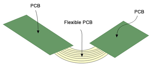
Expensive and complicated discrete interconnection cables can reduce a design's reliability, increase design cost and overall design size. Fortunately there is an alternative in the form of flexible and flex-rigid PCBs. Flexible PCBs can provide you with a cost effective and convenient solution to your design's interconnection requirements, with the added advantage of having the repeatability and reliability of a PCB. Whereas discrete interconnections have inherently different conductor orientations, flexible PCBs hold all conductors in fixed special orientations to each other. This consistency of composition allows for the precise modeling of flexible PCB traces and a more predictable design. Additionally, flexible PCBs can include gold finger contacts allowing for the edge of a flexible PCB to serve as the male portion of a connector and can accommodate high density designs. As such flexible PCBs can be used to replace the vast majority of traditional discrete interconnection solutions while still allowing for a highly modular design.
Beyond providing an efficient means of producing an interconnect solution for a design, flexible PCBs can also accommodate components and be the basis for an entire solution. Using a flexible PCB in place of a traditional PCB can allow for smaller and less conventional PCB designs that are able to fit in housings that would otherwise not be able to accommodate a traditional PCB. Instead of mounting your components to a rigid PCB you can mount then on a flexible solution and they will conform to contoured housings. Furthermore, portions of a flexible PCB can be stiffened with a stiffening substrate to increase the reliability. Finally, flexible PCBs lend themselves to the lightest possible solution, as flexible PCBs are significantly lower in weight per unit area compared to traditional PCBs. Examples of applications that are commonly based on a flexible PCB solution include wearable, digital cameras, medical devices and other small consumer electronics devices.
Flexible PCBs also provide the advantage of being inherently resistant to vibrations. They are often used in automotive devices because of its inherent resistance to vibrations, also well suited to electronics with mechanical components. As such, they are widely used in printers, hard disks and keyboards.
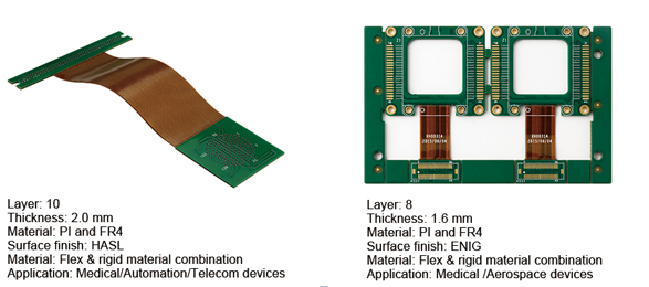
Flex-rigid PCBs present the best of both traditional PCBs and flexible solutions. With a flex-rigid design the interconnection between two boards is built in. Using a flex-rigid solution allows the designer to accommodate three dimensional solutions in a single assembly step. Using flex-rigid PCBs rather than traditional PCBs and discrete connection can reduce the assembly time of the final product and ultimately lead to a more reliable product. The growth of the use of flex-rigid solutions in recent years is a testament to the utility provided by flex-rigid solutions.

Here are two samples of fabricated Flex-rigid PCBs:

The design process for a flexible or flex-rigid solution is very similar to that of a traditional PCB board, with the added caveat that the flexible portion of the board needs to be paid special attention with regards to mechanical qualities. Once the two dimensional layout of a flexible design has been created, it's a good idea to create a mock up of your flexible design using 3D modeling software or to create a paper mock up of the design. Using this method enables you to test whether the design conforms to the mechanical specifications of the flexible substrate. Apart from this, your design does not require a bend radius smaller than that tolerated by the flexible PCB. IPC-2223 can be consulted to determine the minimum bend radius of a particular design.
Other design tips include: Consider staggering traces from layer to layer on flexible circuits to offer higher levels of flexibility. Conductors should always be routed perpendicular to a bend radius to aid in reliability and flexibility. Termination areas should be stiffened using stiffeners. Shielding should be done using a cross hatch pattern rather than with solid planes. Through holes should be kept away from bend areas.
Before sending a design for fabrication, consider that your flexible board is bendable in the design process and design the board to have the highest density possible when nested on the productions board. If bend can be used to achieve a particular dimension then make that bend in the installation and not in the initial design. Finally, using stiffeners with a flexible PCB may be a more cost effective solution than a flex-rigid design. When you only require a low number of layers in a design it may be more cost effective to use a flexible PCB with stiffeners added at critical portions of the board. It's only when your design has a very large layer count requirement that you should consider a flex-rigid solution.
Finally, populating flexible PCBs is a very similar to populating rigid PCBs. Consider the following tips when doing flexible PCB assembly:
• Bake flexible PCBs for an hour before populating them to eliminate any absorbed water.
• Fix flexible PCB to a hard surface to provide dimension stability while soldering to the device.
• When hand soldering devices to a flexible PCB, jump around soldering dense pinned devices to avoid overheating portions of the flexible PCB.
In summary, flexible and flex-rigid PCBs can greatly reduce the cost and complexity of the manufacturing process of you next product. Flexible PCBs are excellent replacements for traditional discrete wiring solutions, offering the repeatability and reliability of PCBs in a flexible form factor. Furthermore, flex-rigid PCBs offer the opportunity to create highly complex three dimensional designs while maintaining low assembly cost, high levels of repeatability and reliability. Simply put, flexible PCBs will allow you to tackle designs that would otherwise be cost prohibitive, overly complex to manufacture or simply impossible. Take your design to the next level with a flexible or flex-rigid based PCB.
Capabilities
Payment Methods
Specials Price
Carriers
Support Hobbyist
Certificate
Customer Support
Follow Us
Tel: 1-905-339-2881
Email: sales@goldphoenixpcb.com , tech@goldphoenixpcb.com
Copyright Gold Phoenix PCB Co., Ltd. 2011 - 2026
Tel: 1-905-339-2881 Email: sales@goldphoenixpcb.com , tech@goldphoenixpcb.com
Quality Control System
|
Products/Service
|
Friendly Links
Copyright Gold Phoenix PCB Co., Ltd. 2011 - 2026


